- Sign In
- |
- Sign Up
- |
- My Quote (0)
- |
- CART (0)

Featuring a 4-channel, 200 MHz high-performance oscilloscope based on UltraVision II technology, as well as up to 8 GSa/s real-time sample rate. It offers a 9" capacitive multi-touch screen, along with a compact and portable design. It integrates 7 independent tools into one, delivering super sample bandwidth ratio and extremely high memory depth.
Featuring a 4-channel, 200 MHz high-performance oscilloscope based on UltraVision II technology, as well as up to 8 GSa/s real-time sample rate. It offers a 9" capacitive multi-touch screen, along with a compact and portable design. It integrates 7 independent tools into one, delivering super sample bandwidth ratio and extremely high memory depth.
This digital oscilloscope is a high-performance oscilloscope model design based on UltraVision II technology. With a 9" capacitive multi-touch screen, it integrates 7 independent instruments into one, delivering super sample bandwidth ratio, extremely high memory depth, and other excellent specifications. It is compact and portable in design, and supports multiple channels, bandwidths, and the upgrade of the analysis software. As it integrates many functions of multiple instruments, different user groups can have more choices in selecting their desired product based on their needs
Features
Functions
Additional Functions (Optional)
Applications
UltraVision II Technology Platform Brings Excellent Specifications
The UltraVision II platform integrates innovative research in the digital oscilloscope's signal processing, data analysis, and waveform visualization, with higher waveform capture rate, full digital trigger technology, and full memory hardware measurement technology. The digital oscilloscope is equipped with the UltraVision II technical platform, and also integrates 7 general instruments in the electronics measurement industry, offering extraordinary user experience.
Higher Reliability and Longer Service Life
The main board circuit of the digital oscilloscope adopts the ASIC chipset, which makes the front-end circuit enjoy a higher integration, the circuit design more simple and reliable. Meanwhile, no relay is added to the oscilloscope, which has prolonged the service life of the oscilloscope to a large extent.
Mainstream Touch Screen Design Offers You Supreme User-Friendly Experience
The 9" capacitive multi-touch screen supports various touch gestures, making it always keep up with the mainstream development trend for screen operation. Various multi-touch gestures such as Tap, Drag, Pinch & Stretch, and Rectangle Drawing are supported, making the measurement actions more smooth, convenient, and easy for user to operate. Meanwhile, the digital oscilloscope still keeps the knob and key operation of traditional oscilloscopes have, optimizing the user-friendly interactive experience to a large extent.
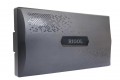
Small Body, Big Use
The innovative physical appearance of the instrument and the thin design in both sides of the instrument not only make its LCD display prominent but also keeps its shape delicate, making it portable and easy to operate.
Super High Sample Bandwidth Ratio
Bandwidth and the sample rate are two key technical specifications that engineers take priority in choosing the digital oscilloscope. Bandwidth determines the maximum frequency that the oscilloscope can acquire. The higher the bandwidth of the oscilloscope, the better the oscilloscope can keep the steep, fast, abundant harmonics components and energies of the signal under test. Whereas the sample rate determines the time interval of the sample points, that is, determines the refinement of the outlined waveforms. Provides a maximum of 8 GSa/s real-time sample rate and 23X sample rate/bandwidth ratio for 350 MHz bandwidth, which makes itself far ahead of the same level products.
While maintaining the super high sample rate of 8 GSa/s, the oscilloscope also has a maximum of 200 Mpts memory depth, enabling itself to capture more events in one acquisition. This provides sufficient time for users to observe while retaining the waveform details to a large extent. Thus, users can not only get the detailed information about the waveforms, but also can take an overview of the waveforms.
500,000 wfms/s Capture Rate
Engineers often have to spend a lot of time and efforts in locating the problem in design and debugging. Therefore, a proper debugging tool will help engineers to work more efficiently. The digital oscilloscope can provide the waveform capture rate of up to 500,000 wfms/s, so that the glitches and infrequent events in waveforms can be quickly identified, greatly improving the debugging efficiency for the engineers.
256-level intensity grading display can reflect the occurrence frequencies of the infrequent events. Its newly added color persistence function can highlight the signal of different probabilities with a different color grading. You can set the persistence time to control the duration time for the waveforms to be displayed on the screen, so that the display capability of the infrequent events can be further enhanced.
Hardware Full Memory Auto Measurement
The auto measurement is the basic tool for engineers to make a rapid analysis of the signals, and it requires more efficient measurement process and accurate measurement results. Supports hardware full memory auto measurement, provides measurements of 41 waveform parameters, supports displaying the statistics and analysis of the measurement results for 10 items. In addition, the auto measurement function also supports auto cursor indicator and measurement range selection. You can also set the threshold for each measurement source independently, making the waveform measurement more flexible. To get a quick view about how to make measurements, we provide you with detailed help documents and diagrams to better illustrate the measurement methods for each item.
Based on the different data sources, auto measurement consists of two modes: Normal and Precision. In Normal mode, the data volume increases from 1 k to 1 M, realizing the optimization of the basic measurement function. In Precision mode, the oscilloscope provides hardware full-memory auto measurement, greatly improving the precision of the waveform measurement.
Hardware Waveform Recording and Playback
The memory depth is one of the key specifications of the oscilloscope. However, whatever high the memory depth, it cannot be guaranteed that all the signals that users are concerned about can be captured in one time. This is especially true for the occurrence of the infrequent signals during debugging design or locating specific events from the long captured complicated signals. In addition, the long memory depth will be bound to reduce the response time for the oscilloscope. The hardware waveform recording and playback function can address this issue.
Provides ceaseless recording and playback for a maximum of 450,000 frames of hardware real-time waveforms. This specification is second to none in the industry. The hardware waveform recording function adopts the segmented storage technology. With the technology, you can set the trigger conditions to make a selective choice in capturing and saving the signals that you are interested in, then mark the time on the signal. This has not only ensured the high capture efficiency, but also prolonged the overall observation time for the waveforms. The hardware waveform playback function enables you to have sufficient time to take a careful view and analysis of the recorded segment of the waveforms.
Hardware Pass/Fail Test
Equipped with hardware pass/fail test function as the standard configuration, which can be used in signal monitoring for a long time, signal monitoring during design, and signal test in the production line. You can set the test mask based on the known "standard" waveform, and then compare the signal under test with the "standard" waveform to display the statistics on the test results. When a successful or failed test is detected by the oscilloscope, you can choose to immediately stop monitoring, enable the beeper to sound an alarm, or save the current screen image. Also, you can choose to continue monitoring.
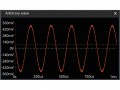
Enhanced FFT Analysis
Can analyze 1 Mpts of FFT, which improves the frequency resolution to a large extent, convenient for you to better analyze the disturbance noise in the circuit under test. To adjust the spectrum waveforms to be observed, set the center frequency and the span; or set the start frequency and the stop frequency. It also provides the peak search function, which can auto mark up to 15 peaks and display their frequencies and amplitudes in the form of a list. Such information and the non-peak section in the frequency-domain cursor measurement can greatly improve the working efficiency of the engineers.
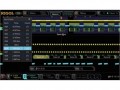
A Variety of Triggers and Protocol Decodings
Provides powerful trigger functions, including Edge trigger, Pulse trigger, Slope trigger, Video trigger, Pattern trigger, Duration trigger, Timeout trigger, Runt trigger, Window trigger, Delay trigger, Setup/Hold trigger, Nth Edge trigger, and serial protocol trigger. These triggers can help engineers accurately and quickly capture and identify the signals of great interest.
The optional serial protocol decoding is capable of decoding 4 serial buses simultaneously. The full memory data analysis and the decoding event table display can help engineers quickly find out the system failure and locate the symbol error waveforms, greatly improving the debugging efficiency of the overall system signals. It also provides optional decodings such as RS232/UART, I2C, SPI, CAN, LIN, I2S, FlexRay, and MILSTD-1553. These serial bus decodings can help engineers make a deep analysis on the waveforms, and they are widely applied to the auto electronics, aerospace, and other fields. Besides, the oscilloscope has a standard parallel bus decoding, which is capable of performing the debugging test for the mixed signals of up to 20 channels (analog channel and digital channel) simultaneously.
Zone Trigger
In face of the complex and variable circuit signal in the circuit debugging, it is easy for us to find the transient occasional exception signals on the oscilloscope with a high waveform capture rate. However, it is not easy to isolate the exceptional signal from the complex circuit signals and trigger them stably. You have to spend more time on the usage of some advanced trigger types, and sometimes even the powerful advanced trigger is unable to make it. It is specially equipped with touch screen-based zone trigger function, which can help users accelerate the signal isolation process. The zone trigger function is easy to operate. You only need to use the specified rectangle drawing gesture to draw one or two rectangular zones on the corresponding signal section, then you can quickly isolate the signal for observation. The zone trigger can work with other 20 trigger types, and it also supports the decoding, waveform recording, and pass/fail test functions. This is conducive to the debugging of the complex signals.
Remote Wireless Control Software
The Web Control software is a standard configuration. You can use the software to migrate the instrument control and waveform analysis to the PC, and then click the mouse to operate easily. You only need to input the IP address of the oscilloscope into the address bar of the Web browser to open the Web Control software. The display of the waveform interface and instrument control in the software are consistent with that in the MSO5000 series. You can use the mouse to tap the keys or knobs in the Web Control interface to complete the waveform control, measurement, and analysis. In the Web Control interface, the basic information of the instrument is displayed, and you can also upload or download the files of the oscilloscope, control with the SCPI commands, set or modify the network status.
User-Defined One-Key Quick Operation
There is a dedicated Quick key on the front panel of the oscilloscope, enabling you to customize the function of the key and complete the commonly used operation quickly. With the customized setting of the Quick key, you can quickly capture the screen image, realize waveform saving, setup saving, all measurement, reset measurement statistics, reset pass/fail test statistics, printing, email sending, waveform recording, group saving, and etc.
| Analog Bandwidth | 200 MHz |
| Rising Time (Typical) | ≤1.75 ns |
| No. of Input/Output Channels | 4 16 input digital channels (PLA2216 probe required) Dual-channel arbitrary waveform generator output (MSO5000-AWG option required) |
| Sampling Mode | Real-time sampling |
| Max. Sample Rate of Analog Channel | 8 GSa/s (single-channel), 4 GSa/s (half-channel), 2 GSa/s (all channels) |
| Max. Memory Depth | Analog channel: 200 Mpts (single-channel), 100 Mpts (half-channel, 50 Mpts (all channels) Digital channel: 25 Mpts (all channels) |
| Max. Waveform Capture Rate | ≥500,000 wfms/s |
| Hardware Realtime Waveform Recording and Playing |
≥450,000 wfms (single-channel) |
| Peak Detection | Under all the time base settings, capture 500 ps glitches |
| Display | Size and type: 9" capacitive multi-touch screen/gesture enabled operation Resolution: 1024 x 600 |
| Power Supply | 100 to 240 V, 45 to 440 Hz |
| Temperature Range | Operating: 32 to 122°F (0 to 50°C) Non-operating: -22 to 158°F (-30 to 70°C) |
| Safety | IEC 61010-1:2010 (Third Edition)/EN 61010-1:2010, UL 61010-1:2012 R4.16 and CAN/CSA-C22.2 NO. 61010-1-12+ GI1+ GI2 |
| Dimensions | 14.45 x 7.87 x 5.12" (367 x 200 x 130 mm) |
| Weight | <7.7 lb (<3.5 kg) |
Click on a category to view a selection of compatible accessories with the RIGOL MSO5204 Digital Oscilloscope, 200 MHz, 4 Channel.


